So far we’ve looked at some boolean operators in an abstract sense, pretty much as mathematical operators. However, they have a very real and tangible application to older computer-related circuitry. Before we get into the bulk of it we need to establish a base understanding of an electric gate.
In the gate shown below, we have a piece of a circuit in which physical “gates” help control the flow of electricity.
http://www.technologystudent.com/images2/dig4a.gif
Based on basic circuit properties, when there is a path from the battery to the light (closing the circuit), the light can switch on. Each of the two gates would have a control sent in that represents one of two input variables. Based on the picture, can you tell what logical operation is represented?
We can use physical gates that enact the outputs of every logical operator. As shown in the image above, parallel gates make an OR operator. The circuit is closed when either gate (or both) is connected. Sequential gates (as shown below) make an AND operator. The circuit is only complete when both of the gates are closed.
http://www.technologystudent.com/images2/dig3a.gif
To achieve some of the other operators requires some creative thinking but is quite easy to make once you know what you’re doing.
https://encrypted-tbn0.gstatic.com/images?q=tbn:ANd9GcR5k0ACB5Moe0QAYRIBDuZ96Q9xY4Ypxk5JI8BowyeQHJxkEZaD
These circuits are great when working with various engineering applications, but it is incredibly unreasonable to make physical circuits when planning out large-scale ideas. Engineers who work with such things want to be able to come up with a design without wasting physical resources before their ready, so we have a standard for notation for such gates. Rather than physical gates, these are called logic gates and simply represent the corresponding logical operators. Each operator has its own gate symbol.

These gates work identically to the symbols you’ve been using (with the addition of the NAND, NOR, and XNOR) regarding their input-output tables. Notice that all of the “NOT” gates have a circle attached to one end. In full logic-gate symbolization, the circle is what is reversing the value. So some uses of logic gates include a circle on an input even, which just reverses that input.
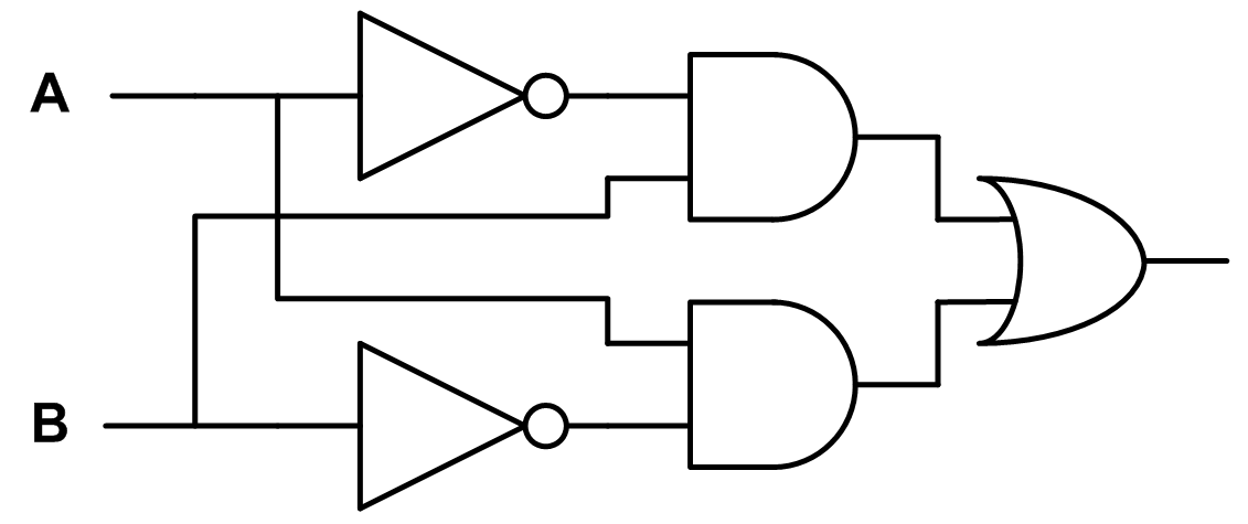
When working with these gates, you typically draw connecting lines between them to representing pushing a value through. The example below shows how multiple gates can be applied in sequence (one feeds into another) or in parallel (no connecting lines between them, but using shared input information) to make larger ideas.
Try reading the diagram to interpret what logical statement it is enacting. Connecting lines show a value’s “path” from one place to the next. When lines cross some diagrams have different ways of showing what’s happening, but if two wires meet perpendicularly assume that they are only crossing due to limitations of the image and the values themselves are not affecting each other at that spot. Additionally, the letters at the left side represent the initial input variables, with the ending wire at the right side being the ending output.
(If you struggle with it, one way that sometimes helps is to start at the gate closest to the end and work backwards, liberally using parentheses to group things together.)
https://anubnair.files.wordpress.com/2010/12/high-z_solution_02.png
It will take a bit of practice to get used to which symbol means which operation. One great way to get that practice is this game from Khan Academy. In it, you place logic gates by dragging them from the box at the top into the play area. Then connect inputs and outputs by dragging from one node to another. The goal for each level is to make a gate system that matches the truth table in the upper right. By default, green is “on” and grey is “off” so use the table as your guide for what you are trying to make.
← Previous PageNext Page →